Digital Electronics: Data Formats and Classification of Registers
Best comment
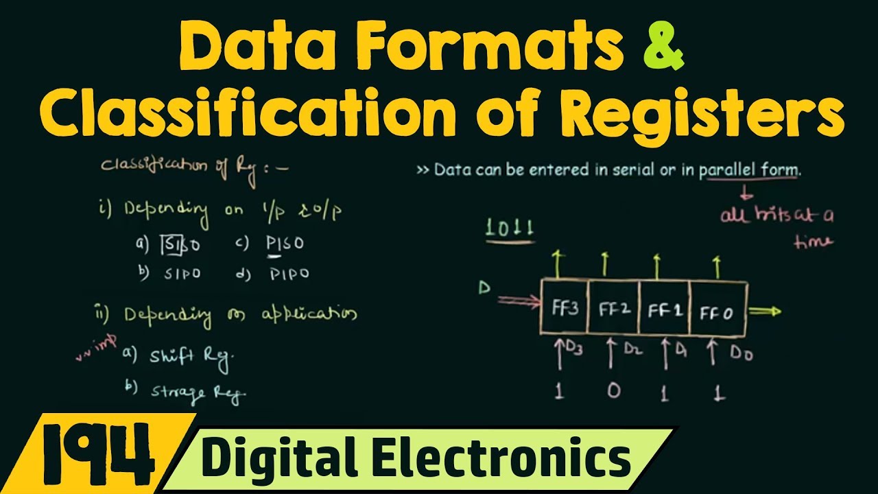
- Shailesh Pawar: siso = shift registers or not
- Chinnari 852: please upload a/d d/a converters and op amp
- Indu Kumari: pls upload some vides on memory orsend me a link
- chinnugadu 1919: Very useful
- evan aw: yeah i was wondering about the same thing. But i think that since he didn't mention anything about the type of the clock, the timing diagram is not correct nor wrong. But if u were assuming that the FF is negative edge triggered, the timing diagram in the serial form should be up to the fourth pulse, while in the parallel form each input up to the 1st pulse.
- atul rana: You are lord of teaching
- Ashish Daniel: thanks
- Deb Roy: "Spatial Code" not "Special Code"
- evan aw: +Electrical Engineering at least he contributed something, wbu? lol
- Manoj Sai: +Neso Academy sir please provide adc and dac lecture, thankyou forr this lectures
- Electrical Engineering: if you already know everything then what the fuck are you doing here ?
- Uiet chandigarh Velfies: sir plz make videos on DAC and ADC converter plzz
- Adwait Upadhyay: Is SIPO is storage register too??
- Nicklaus Settoon: you are my savior
- Reena Thomas: Good teaching...
- evan aw: shouldn't the input of D be 1, 1, 0, 1 for the serial form? if the input was 1(1st tick), 0, 1, 1, the data interpreted in the flip flops would actually be in the inverse direction (1101) or in other words first in first out. the clock of the flip flop should also be determined, whether it is positive or negative edge triggered(and the timing diagram of the serial input D should adjust accordingly) which means, the D will change only after 1 full period of each pulse, not half of it.
- RAMESH DUMALA: Adding Bubble at the clock indicates -ve and arrow indicates the edge triggering so o> adding to clock means it is -ve edge triggering flop flop
- Chinnari 852: your teaching skills excellent
- Kshitij Vengurlekar: Thanks
- Sarita Sharma: I am still in confusion ...Why only one clock pulse is used on PIPO?
- Sohel Rahman: Thank you so much for these videos! Literally saved my grade this semester <3
- Rupesh Chandrawanshi: good explaination
- Syed Moinuddin: Hmm
- Basabi Singha: Is SISO and shift register the same thing?
- Hanuman ais: Please engneering electromagnetics upload please
That is difficult
- amrutha bindu: sir please give the pdf notes about "Digital Circuits"
- Krishna Mishra: I could not find the A to D and D to A, please help me
- Omar Ahmed: In the first part of the video, why the inputs were drawn, on the time diagram, up to only the second clock? Shouldn't they be up to the fourth clock for serial format and up to the first clock for the parallel format?
- Aditya Inamdar: very good lectures
- Sourabh Jangid: Really suprised such high quality videos are free of cost
- Sherry Goel: It is not "special" code,it is "spatial code"
- PRATIK GUPTA: my favourite.....thank u very much sir!!
- raj gandhi: In anand kumar it is given that parallel in,parallel out is Shift Register?
- ashwini ojha: how can we enter 110001111 in shift right and shift left register
- Pavan Nadagoudar: sir 1011 is stored at every positive edge or negative edge of the clock, but u made at every change in clock which is like the latch
opertaion
- Abhinav Sharma: nice lol
- vinit kothawade: it is temporal code and spatial code (not special code)
- Aakash Verma: sir, as q3 is connected to d2 so, when we get q3 as 1 (in first cycle) d2 should also be 1
- Neso Academy: +Shailesh Pawar SISO is an abbreviation for Serial Input Serial Output Shift Register.
Data Formats and Classification of Registers |
| 271,682 views views | 468,989 followers |
| 1,009 Likes | 1,009 Dislikes |
| Education | Upload TimePublished on 11 Apr 2015 |
|
Không có nhận xét nào:
Đăng nhận xét